Platform Applications
The frame structure can also power the platform.
Structural batteries unite chassis and energy storage. Sasung Power cells integrate into load-bearing EV, robotic, and UAV structures without the mass of a separate battery bay.
Electric Vehicles
Floor pan integration without a battery bay.
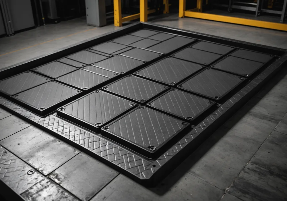
Conventional EV packs sit below the passenger floor as sealed modules, adding mass and structural complexity. Sasung Power cells bond to floor pan substrate as a load-bearing layer, removing conventional enclosure, mounting hardware, and thermal-management volume.
Floor pan integration provides approximately 23% system-level mass reduction versus a comparable capacity pack-in-bay architecture. The BMS manages charging through the floor pan's torsional and bending loads during operation.
- Floor pan bond: co-cure or adhesive-bond onto metal or composite substrate
- Load case: torsion up to 4000 Nm, bending up to 18 kN
- Operating temperature: -20 C to 65 C
- Integration depth: 6-14 mm, depending on cell format
Bipedal Robotics
Structural legs store energy while carrying weight.
Bipedal robots treat batteries as payload, reducing capacity for tooling, sensing, and actuation. Placing energy storage inside structural leg members turns dead payload into a dual-function architecture.
Sasung Power cells fit inside hollow carbon fiber leg tubes as liner layers. The leg carries compressive and bending gait loads while the liner supplies joint actuators through embedded bus bars. The BMS tracks each cell through cyclic gait loading.
- Integration target: hollow carbon fiber or aluminum leg tube members
- Gait load: 2-8 Hz cyclic compressive-bending, variable amplitude
- Per-leg capacity: 0.8-2.4 kWh, depending on tube geometry
- BMS update rate: 10 ms to track per-cell state across gait phase
Gait cycle frequency handled by BMS per-cell update loop
Per-leg capacity range across tube geometry variants
Integration target: liner layer within carbon fiber or aluminum leg members
UAV and Micro-Mobility
Airframe and fuselage as energy store.
UAV range is constrained by battery mass fraction. A conventional fuselage-mounted battery adds structural dead weight because the shell must independently carry its load case around the payload bay.
Integrating Sasung Power cells into UAV fuselage panels makes the shell the battery, uniting structure and energy storage. For multi-rotor platforms in the 10-40 kg class, it adds 18-35 minutes of endurance on a standard inspection profile without increasing all-up weight.
- Platform class: 10-40 kg MTOW fixed-wing and multi-rotor UAV
- Endurance gain: 18-35 minutes on standard inspection profile
- Panel bond: co-cure with prepreg skin or adhesive-bond post-cure
- Micro-mobility: scooter deck, e-bike downtube, cargo frame rail formats
Endurance gain on standard inspection profile at equivalent all-up weight
UAV platform class range for fuselage panel integration
Fuselage panel, scooter deck, e-bike downtube, cargo frame rail
Integration Guide
From concept to bonded structural cell in six steps.
Sasung Power follows a defined scoping and qualification process with integration partners. The first four steps occur before hardware is committed to fabrication.
Steps 1-3: Scoping
Load case review: Platform structure and operating load envelope are compared with cell qualification data. Sasung Power verifies bending, torsion, and compressive loads fall within the qualified range for the target cell format.
Geometry fit: Cell format, bond layer specification, and bus bar routing are checked against platform CAD. Clearance and substrate compatibility issues are resolved here.
BMS software integration: HAL implementation is completed for the target MCU and checked against the BMS communication protocol. A functional prototype with cell-level telemetry is required before proceeding.
Steps 4-6: Qualification
Sample build: A bonded structural cell assembly is fabricated for the target geometry. The BMS is installed and validated against the qualification load protocol.
Combined load test: The assembly completes mechanical and electrochemical load qualification, confirming cycle life, fault detection, and charge management across the platform's operating envelope.
Production readiness: Final documentation package includes bond layer specification, BMS firmware version, and qualification data against agreed acceptance criteria. First article inspection is co-managed with the partner's quality team.
Start the Conversation
Share your platform and load case.
Integration feasibility depends on platform geometry, load envelope, and energy requirements. The scoping discussion is confidential and requires no commitment.