Cell Architecture
Carbon fiber that carries the vehicle and its charge.
Structural cells designed to carry mechanical loads during charge cycling. No pack enclosure. No dead mass. Electrochemical performance remains intact.
Materials
Carbon fiber composite with integrated ionic pathways.
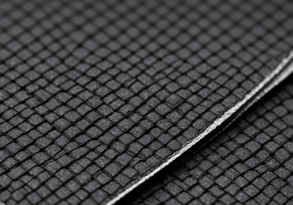
Sasung Power structural cells use a unidirectional carbon fiber composite (CFC) layup for the outer load-bearing skin. Fiber direction maximizes in-plane stiffness while preserving controlled porosity channels for electrolyte flow between layers.
The electrochemical stack uses LFP (lithium iron phosphate) chemistry for a flat discharge curve and thermal stability under flexural load. The LFP cathode maintains performance across bending floor panels, torsional robotic-limb load paths, and delivery-vehicle frame impacts.
A ceramic-coated polymer separator preserves ionic conductivity under axial compression up to 180 MPa, a requirement not previously needed across most cell formats.
Mechanics
Dual function under load.
Structural battery design links mechanical stress concentrations with high-current electrochemical pathways. Elevated tensile strain accelerates dendrite nucleation, while bending coupled to charge distribution causes uneven capacity fade across the cell face.
Sasung Power addresses this with three measures: a strain-relief composite layer between current collector and separator; BMS software that adjusts charge rate using real-time strain proxies from impedance telemetry; and geometry tuned for bending-dominant loads instead of conventional prismatic flat-compression formats.
Conventional lithium cells use uniaxial compression inside a pack enclosure. Bending creates tensile and compressive faces. On the tensile face, graphite anode layers separate, trapping lithium in delaminated pockets. Capacity loss per cycle increases as delamination spreads.
Sasung Power's LFP cathode has isotropic crystal structure at particle level. With the strain-relief interlayer, it removes the main failure mode preventing many chemistries from structural integration. Testing under 3-point bending at 40% depth-of-discharge shows less than 0.5% capacity loss per 100 cycles at design load.
Specifications
Cell specification data.
Characterization values for the Gen-2 cell format. Operating limits cover combined mechanical and electrochemical loads.
| Parameter | Value | Unit | Note |
|---|---|---|---|
| Gravimetric energy density | 187 | Wh/kg | 0.5C discharge at 25 C, no mechanical load |
| In-plane elastic modulus | 8.1 | GPa | CFC layup, 0-90 biaxial fibers |
| Nominal voltage | 3.20 | V | LFP flat plateau at 50% SoC |
| Voltage range | 2.50 - 3.65 | V | Charge cutoff, discharge cutoff |
| Operating temperature | -20 to +55 | C | Full capacity range, derated below -10 C |
| Max continuous charge rate | 1C | 2C fast-charge operation available above 15 C ambient | |
| Cycle life (no mechanical load) | 2000+ | cycles | To 80% capacity at 0.5C / 0.5C, 25 C |
| Cycle life (combined bending load) | 1400+ | cycles | 3-point bend at 40% DoD, design load amplitude |
| Compressive axial limit | 180 | MPa | Separator preserves ionic conductivity to this limit |
| Cell format | Flat plate | Custom dimensions available for pilot partners |
Fabrication
Formulation to calibrated cell.
Five stages combine composite manufacturing and electrochemical cell production in one production run.
Cell chemistry preparation
LFP cathode and graphite anode slurries use binders selected to adhere to the carbon fiber substrate through repeated flex cycles. Particle-size distribution is adjusted to set ionic pathway density within the composite geometry.
CFC layup
The CFC outer skin is assembled in a controlled-atmosphere layup room. Fiber direction follows the customer's load-path model. The strain-relief interlayer is co-cured with the composite, removing the bond line between structural and electrochemical elements.
Electrolyte infusion
Vacuum infusion introduces electrolyte into the pre-cured cell assembly. The process is adjusted to the porosity created by each customer's fiber orientation, since layup schedules produce different infusion rates. Impedance sweep verifies uniformity before sealing.
Formation cycling
Initial charge and discharge cycles run at low C-rate and controlled temperature to form the SEI (solid electrolyte interphase) layer. Sasung Power also performs formation under light compressive pre-load, creating a more stable SEI at the composite-electrode interface.
BMS setup
Each cell is measured for its OCV-SoC curve across the customer's expected operating temperature range. Calibration data is entered into the BMS firmware before shipment. Structural-module cells are matched to within 2 milliohms internal resistance to reduce balancing current under load.
Comparison
Structural cells compared with pack architectures.
| Parameter | Structural Battery (Sasung Power) | Conventional Pack | Structural + Add-on Pack |
|---|---|---|---|
| Total system mass contribution | Net neutral, structure replaced | +18-25% of vehicle dry mass | +8-12% of vehicle dry mass |
| Volume overhead | Zero, the cell is structural | Housing, cooling, enclosure | Less housing, partial cooling |
| Range gain at equal energy budget | 12-18% vs conventional baseline | Baseline | 5-8% vs conventional baseline |
| Maintenance access | Structural repair required | Module swap | Hybrid: swappable pack, bonded structural cells |
| BMS complexity | High: strain proxies at each cell | Moderate: pack and module level | High: dual systems |
Engineering
Contact the engineering team.
Review specifications, analyze load paths, and scope BMS integration for your platform. No generalist sales call, you connect directly with the cell engineers.